

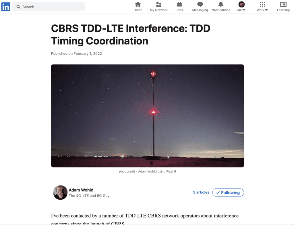
Back in February 2022, Adam Wohld wrote an article on LinkedIn called CBRS TDD-LTE Interference: TDD Timing Coordination about a growing issue with CBRS networks. More and more people that are deploying CBRS networks are coming from the Enterprise networking world and not the cellular industry. The lack of deep understanding of the 3GPP Standards is introducing potential interference issues as more people build CBRS networks that operate in the GAA Tier. My WLAN Pi Pro plus a 5G Modem helped me find some potential interference within range of my CBRS network.
My last post showed my WLAN Pi Pro with a 5G Modem War Driving around my community capturing PCAPs of the LTE Bands. What I captured during that wardrive has findings that are rooted in that article by Adam Wohld. Capturing that traffic showed that my network was misconfigured potentially causing interference problems as the network grows.

Timing and configurations are very important for optimal performance. If you plan on building a CBRS network dig into the technology or you might be forced to dig into it later.
As I mentioned in a previous post, I started this project because of my studies of the CWAP. For those who are unfamiliar, the CWAP exam digs into the details of Wifi Networks, including Frame Captures and Spectrum Analyzers, pulling apart the details of the Wifi Standards.
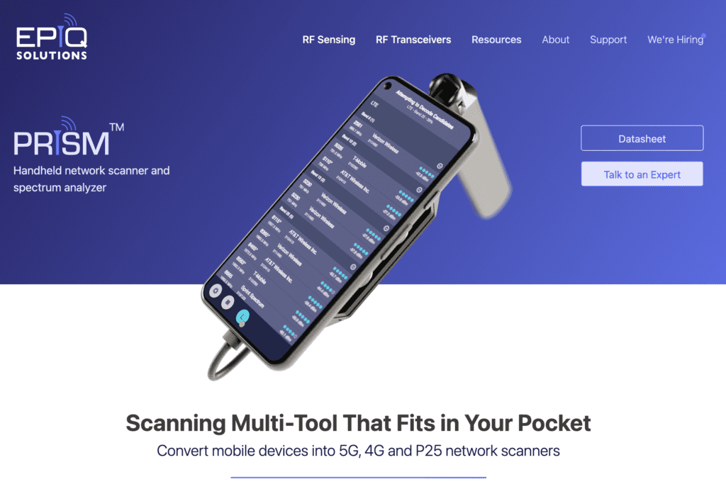
While studying for the CWAP, I wondered how I could apply the same tools and ideas to the CBRS world. Tools built specifically for CBRS are limited, and carrier tools are uber expensive for my small educational budget to explorer. As part of our larger user group, we are looking to purchase the Epiq Prism that Adam Wohld talks about, but I wanted to see if there was other ways to build such tools for my own use. Capturing LTE air interface traffic unlike capturing Wifi management and control traffic is more tricky than putting a Wifi card into monitor mode with Wireshark.
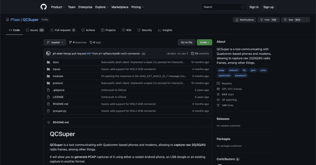
That exploration lead me to finding QCSuper on Github. Back in 2019, apparently QCSuper was created as a way to exploit the Diagnostic Port on Qualcomm LTE Modems of Rooted Android Phones. The tool works for other technologies such as 2G, 3G, and Wimax. It doesn’t seem to work with 5G yet. I didn’t have a Qualcomm based Android phone that I wanted to Root, so I decided to see if the tool would work with a Raspberry Pi with a M.2 Qualcomm X55 Modem leading to my CBRS Pi Project and now my WLAN Pi Pro + 5G Modem Project.
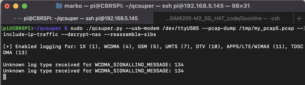
My previous post about CBRSPI Killer Applications goes into installation and operation of QCSuper. This post is going to dig into what QCSuper can do for a CBRS Wireless Engineer and findings from my own WarDriving experience with a WLAN Pi Pro + 5G Modem running QCSuper.
LTE Frame Types
QCSuper captures five main logical channel types of LTE frames: BCCH, PCCH, CCCH, DCCH, DTCH. The developer of QCSuper wrote an article that discusses these captured frames. Also for a more in-depth reading, Aruba has written a good series of white papers about CBRS from the perspective of a Wifi Engineer. The first white paper goes into the Radio, which has a good overview of some of the time potential issues discussed later; the second white paper digs into the Signaling and Control, which has a good introductory to these frame types; and the final white paper explorers the network implementation and design; which discusses the scheduler and other design considerations with CBRS.
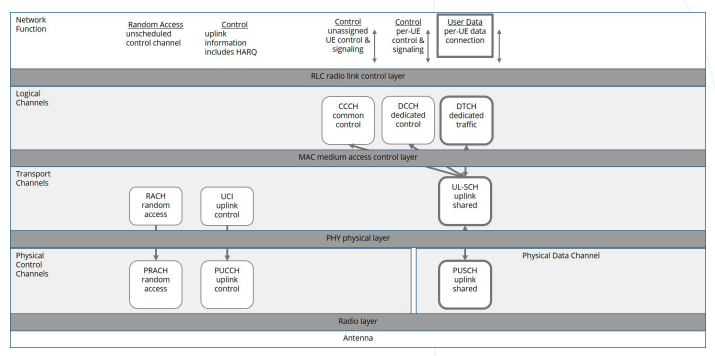
The following diagrams for downlink and uplink comes from that second white paper, Signal and Control article by Aruba. With QCSuper, we are capturing frames in the layer 3 logical channels level.
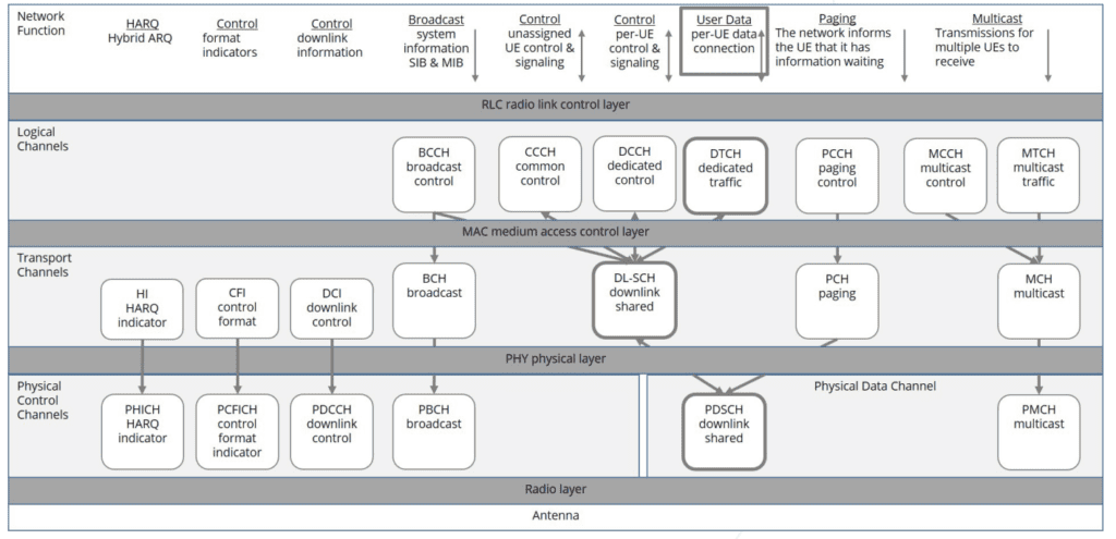
Below are some basic explanations of the different frame types with screen shots from my QCSuper captures in Wireshark.
Broadcast Control CHannel (BCCH) contains the network information similar to a Beacon in the Wifi world. Frames containing the MCC and MNC are BCCH Frames. The broadcasts are sent in fragments called SIBs and MIBs. QCSuper can capture individual fragments or rebuild the SIBs in the PCAP files. BCCH frames only exist in the downlink direction.
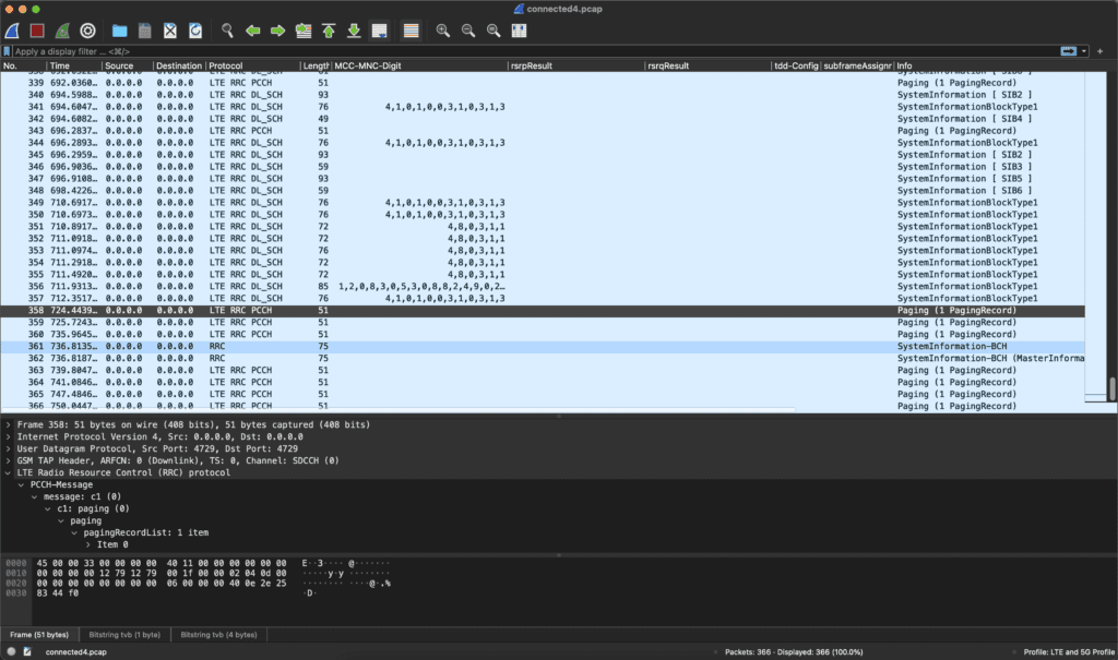
Paging Control CHannel (PCCH) tells a device to wake up from power save mode because it has data to receive from the Radio such as a phone call or a text message. The example frames below are called PagingRecords. This is like Wifi beacons containing TIM information of the AID of stations that need to wake up to receive traffic. PCCH frames are downlink only.
Common Control CHannel (CCCH) requests additional radio resources for signaling and control. This handles traffic such as when a device initially joins a network called a RRCConnectionSetup frame in the example below. These are like the various frames involved when a device joins a BSSID in Wifi. These frames are found in both downlink and uplink directions.

Dedicated Control CHannel (DCCH) additional signaling information. DCCH frames can communicate the capabilities of the User Device (UE) to the eNodeB Radio or may show a Measurement Report that portrays the received RSRP and RSRQ of a device as shown in the examples below. DCCH are found in both downlink and uplink directions.
Dedicated Traffic Control CHannel (DTCH) contains the data and voice traffic. This is encrypted, the payload is unreadable, and isn’t captured by QCSuper. Voice and Data are broken into different sub channels stemming back from the 2G world when data was introduced to cellular networks. My captures have yet to capture any DTCH traffic. Since this contains the data and voice traffic, obviously DTCH can be found in both downlink and uplink directions.
Multicast CHannel (MCCH) and Multicast Traffic CHannel (MTCH) are meant to broadcast TV signals over cellular and are not used in CBRS Networks. These are found in the downlink direction only as multicast traffic is destined for multiple devices at the same time.
Troubleshooting with Frame Captures
Returning to Adam Wohld’s article, he discusses the MCC, MNC, SIBs and subframeAssignment fields. Guess what, QCSuper can capture all that information in the above frame types.
CBRS operates with a Public Land Mobile Network (PLMN) of 315010 unless an organization obtains their own PLMN. The PLMN is made up of the Mobile Country Code (MCC) and Mobile Network Code (MNC), so for CBRS Networks the MCC is 315 (signifying USA) and the MNC is 010. The 315010 code is a dedicated code that signifies the LTE/5G network is a Private Network operating in the CBRS Band within the USA. All LTE/5G networks have PLMN codes.
QCSuper can capture those BCCH broadcast frames. I have captured privateLTE and carrier’s FDD and TDD BCCH Frames for CBRS, Verizon, AT&T, and T-Mobile using QCSuper containing each network’s individual PLMN codes.
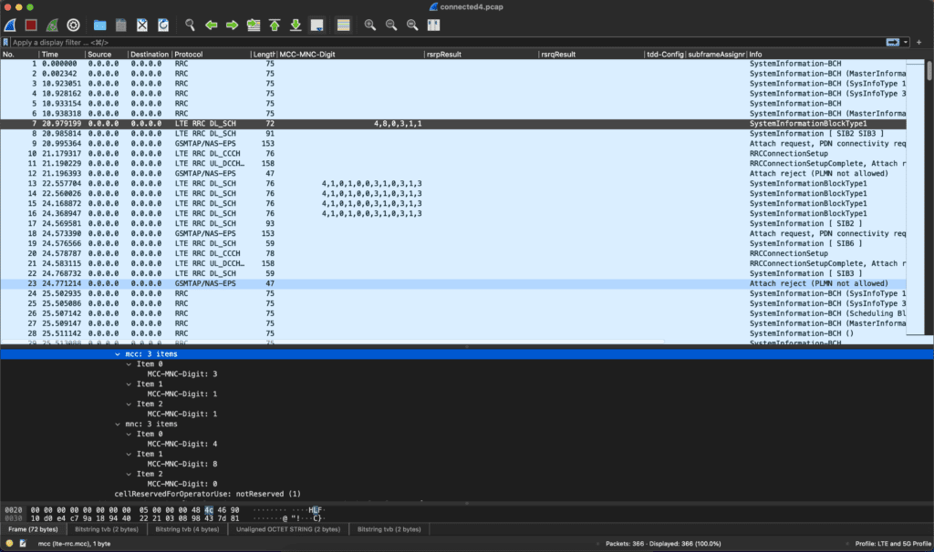
The example capture below shows the MCC is 311 and the MNC is 480. You can see that the PCAP columns in Wireshark shows them backwards (4,8,0,3,1,1) as they are actually captured as individual MCC-MNC-Digits in the frame contents. The website MCC-MNC.com has a list of MCC and MNC that you can use to determine who the PLMN from the BCCH Frame came from. If you look up 311 480 in their table you find that this specific PLMN is owned by Verizon.
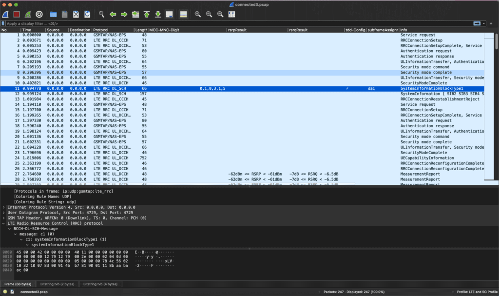
The next information that Adam discusses are SIB1 and SIB2. As I explained above, the LTE Standard breaks the BCCH Frames into Fragments or System Information Blocks (SIBs). QCSuper captures the SIBs in their fragmented state but has a flag that can reassemble them. The captures above show many different SIBs, containing different signaling data.
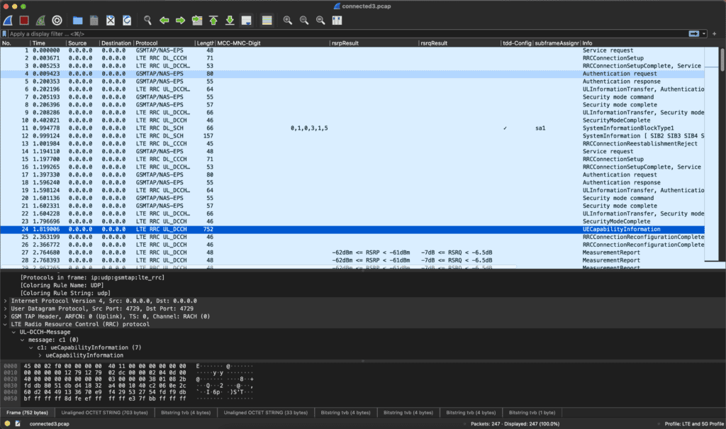
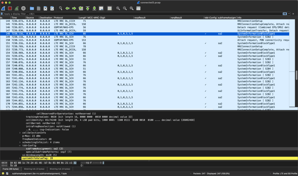
During my WarDriving adventure, I captured BCCH SIBs containing a subFrameAssignment field. Those frames had a MCC and MCN codes of 315 010 so I knew they were a CBRS network and most likely my network. I added Columns in Wireshark to show frames that have the MCC-MNC-Digit, rsrpResult, rsrqResult, “tdd-Config” field signaled with a checkmark, and the “subframeAssignment” field to help me find the information quicker, as you can see on the selected frame.
TDD Subframe Assignments
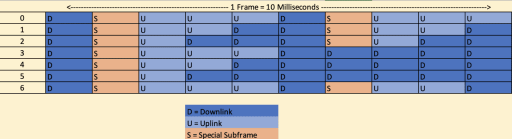
As Adam Wohld talks about, CBRS uses OFDMA to split up the channel into TDD chunks according to a pattern as show in in the chart below from his post. The subFrameAssignment (rows) are the configured pattern while the Subframe Number (columns) are the timing chunks dedicated to Uplink, Downlink, or Special within the channel. Switching from Downlink to Uplink requires a Special Subframe while switching from Uplink to Downlink does not require it. More details about the Subframe Assignments can be found here or in the first white paper from Aruba, “CBRS, The Radio”.
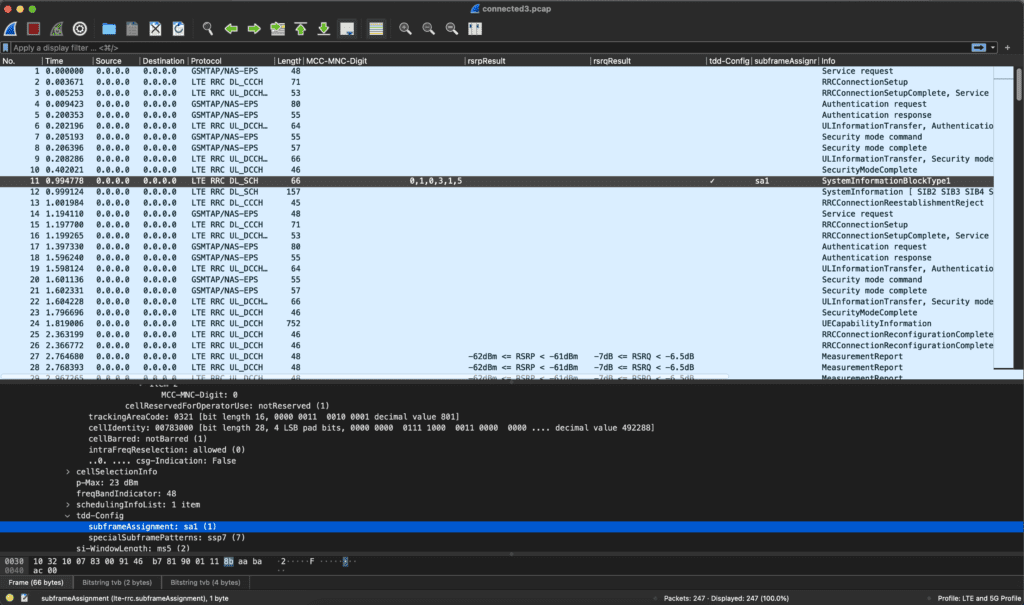
My WarDriving QCSuper captures showed results for both subframeAssignments sa1 and sa2 within MCC/MNC 315 010. One radio is set to Uplink on subframe 3 and 8 while the other radio is set to Downlink on those subframes. These two patterns can cause timing and interference issues if they are on the same channel. While one radio is allowing uplink traffic from a client, the other radio is sending downlink traffic causing potential collisions and interference. As I said before, LTE/5G networks are scheduled and timing is critical to that scheduling.
Basically, sa1 is balanced between upload and download, while sa2 is more heavy on the download and less on the upload. Considering the majority of traffic is download, setting the subframeAssignment value to sa2 gives a better performance on the download. Most networks will benefit from this setting. Usually the default is sa1, hence why this can cause interference issues if you don’t understand how the technology works.
Real World Interference
In thinking about this, I realized that our indoor and outdoor radios were configured differently for this frame pattern. We are using one brand of radios for Indoor at my office in the center of town and another brand of radios for outdoor at the neighboring school district on the edges that are broadcasting into the community.
The fact that the radios are indoors vs outdoors helps explains the lack of interference issues. I also haven’t noticed any interference issues because our outdoor radios (sa2) are operating on PAL licensing and my indoor radios (sa1) are operating on GAA on different channels, so they aren’t interfering with each other. If these radios were to be assigned the same spectrum EARFCN by the SAS provider, these would definitely be stepping on each other and there would be noticeable interference. This is still a misconfiguration and as additional CBRS radios are installed within range, this will become a bigger issue on my network.
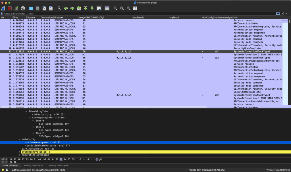
To fix the problem, I changed on the radios at my office to sa2 then collected traffic again with QCSuper. As the capture below shows, now my office radio is set to subframeAssignment “sa2” and matches the outdoor radios.
This is only one troubleshooting use case that I have found so far for the utility of using QCSuper and the WLAN Pi Pro. As I dig into the packet captures, I’m discovering and learning details more easily understood from seeing live packet captures than reading about them in a book.
I was pleasantly surprised to find that I was able to capture and troubleshoot with a Raspberry Pi or the WLAN Pi Pro and a simple 5G USB Modem the same data as the device discussed by Adam Wohld.
QCSuper doesn’t solve all the problems. The Physical Layer 1 analysis through a Spectrum Analyzer is not shown by QCSuper. Also another related item I’m finding is it doesn’t capture the EARFCNs or what band the traffic is captured on as those are physical layer data that is not passed up to the Logical Channels. So I’m exploring other tools like a PCI Scanner, which is similar to a Wifi Analyzer tool. For the Spectrum Analysis, I’m exploring Software Defined Radios (SDR) and a bunch of different applications.
One of my next projects is to look at another LTE Capture program called SCAT: Signaling Collection and Analysis Tool. https://github.com/fgsect/scat I’m going to see if I can get anything different than QCSuper or if it is easier to use.
As I dig into these additional items, I’ll continue to share what I find in my future blog posts.