
In my previous post, I talked about using QCSuper to capture LTE packets on the AirInterface of my WLAN Pi Pro. Since that post, I’ve discovered a few additional things of note including a new tool. Plus, I decided to attempt to use a regular WLAN Pi to see if I could get the drivers to install and show me the same results as my WLAN Pi Pro.

To begin, the regular WLAN Pi worked almost as well as the WLAN Pi Pro. Obviously the regular WLAN Pi doesn’t have a battery or the processing power as the Pro. That makes it much less mobile, but its compact size is an added bonus. A battery pack can help with some of those limitations. Installation was the same as before for installing QCSuper. Then I found another tool that added some new functionality for my device, SCAT.

SCAT: Signaling Collection and Analysis Tool
While playing with QCSuper, I kept reading about the need for a PCI Scanner to supplement the packet captures. QCSuper is great to show the packet capture details, but it is difficult to compare one network to another quickly. As I talked about in my last post, Adam Wohld used an Epiq Prism PCI Scanner to initially find the interfering networks. A PCI Scanner is similar to the Wifi Analyzer tools on Android or Wifi Explorer on a Mac. It shows you a list of available LTE/5G networks that are found from listening to the spectrum. Because LTE and 5G can cover a wide range of spectrum bands, usually PCI Scanners don’t show a graphical view on the networks. It usually just lists the network with different information such as N/EARFCN, PCI, RSRP, and RSSI.
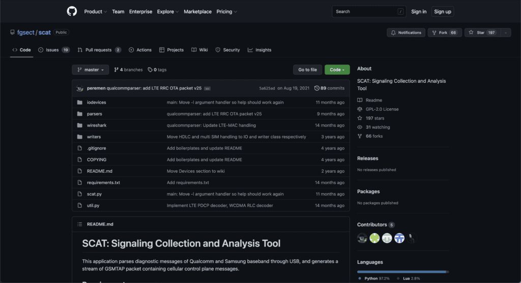
From my research, I found SCAT: Signaling Collection and Analysis Tool, a tool that operates similar to QCSuper but can display EARFCN, PCI, Measured RSRP, and Measured RSSI while running a packet capture. So I had to jump in and test it out. In some ways, SCAT is becoming my go to tool over QCSuper; although, I’m getting some slightly different results from QCSuper. So, I’ll probably keep both tools around in my arsenal.
Installing SCAT is straight forward. If you have QCSuper installed, all the prerequisites should already be installed. Make sure the drivers for your Qualcomm modem are installed, ensure that python3, python3-pip, pyUSB, and pySerial are installed, then use Git to download the SCAT tool from Github. That’s it.
wlanpi@wlanpi:~/$ git clone https://github.com/fgsect/scat.git
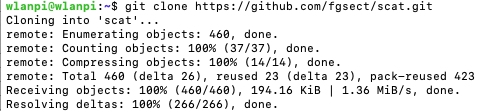
After the prerequisites are installed and you have the tool downloaded, move into the scat directory with the cd command. Inside the scat directory you can run the tool from terminal or ssh with a simple command:
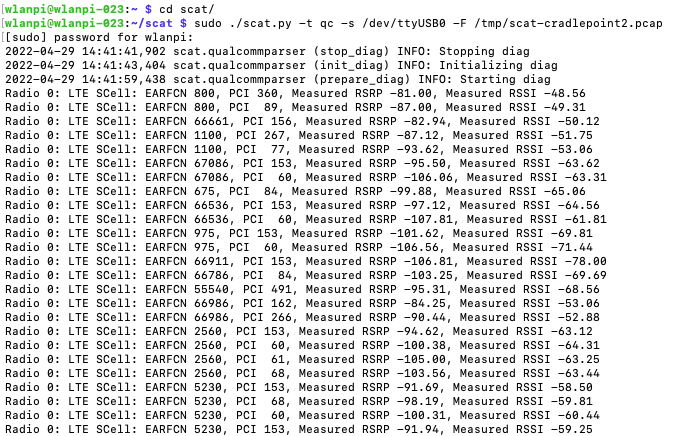
wlanpi@wlanpi:~/scat$ sudo ./scat.py -t qc -s /dev/ttyUSB0 -F /tmp/scat-capture.pcap
What this command is doing is that it first calls the scat.py script. The -t qc flag tells the tool you are using a Qualcomm modem. The -s /dev/ttyUSB0 tells it to use a serial connection just like QCSuper. Although, USB connections are possible with SCAT, I have been unable to get it to work. There doesn’t seem to be a difference between using a USB or serial connection. Then the last flag -F /tmp/scat-capture.pcap tells it to create a .pcap file in the /tmp directory. If you just want to use SCAT as a PCI Scanner, you can omit the -F /tmp/scat-capture.pcap command, and it won’t log to a pcap file.
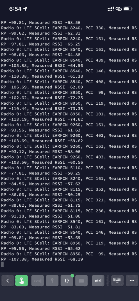
Once you run that command, your terminal or ssh session will begin outputting similar information to below:
You can kill the program with Ctrl-C. If you browse to the /tmp directory you will find a .pcap file just like with QCSuper. Transfer that file to your computer or open it within Wireshark on your linux computer. You should then have a LTE Packet Capture just like QCSuper.
You can also pipe the output of the terminal showing the PCI Data to a file by adding a > /path/to/filename.txt to the end of the command. When you pipe it, nothing will be printed to the terminal, but the command is working. Open the file and it looks like the below, just like a terminal.
sudo ./scat.py -t qc -s /dev/ttyUSB0 -F /tmp/scat-test.pcap > /tmp/pci1.txt
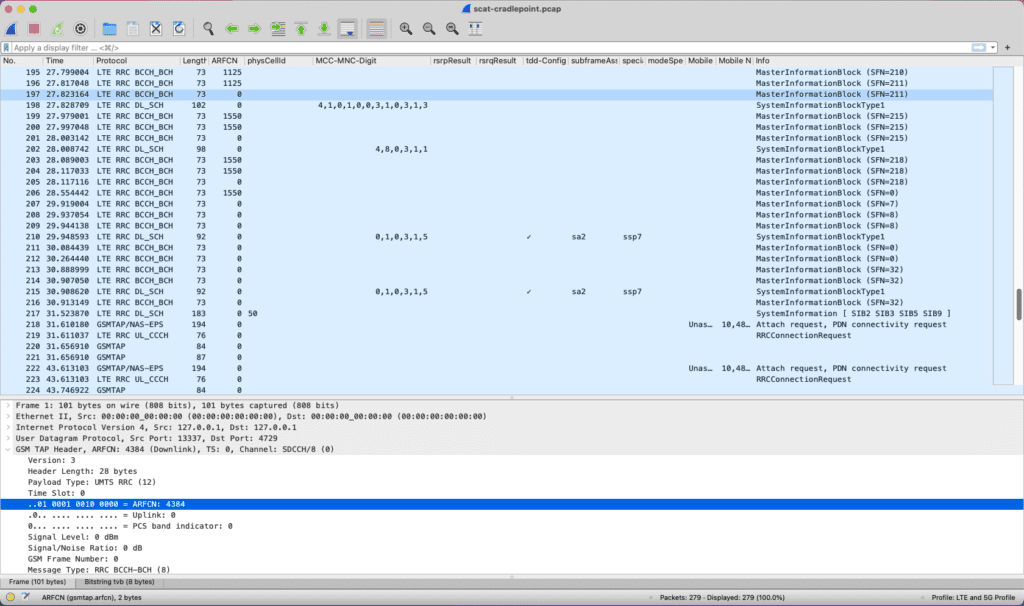
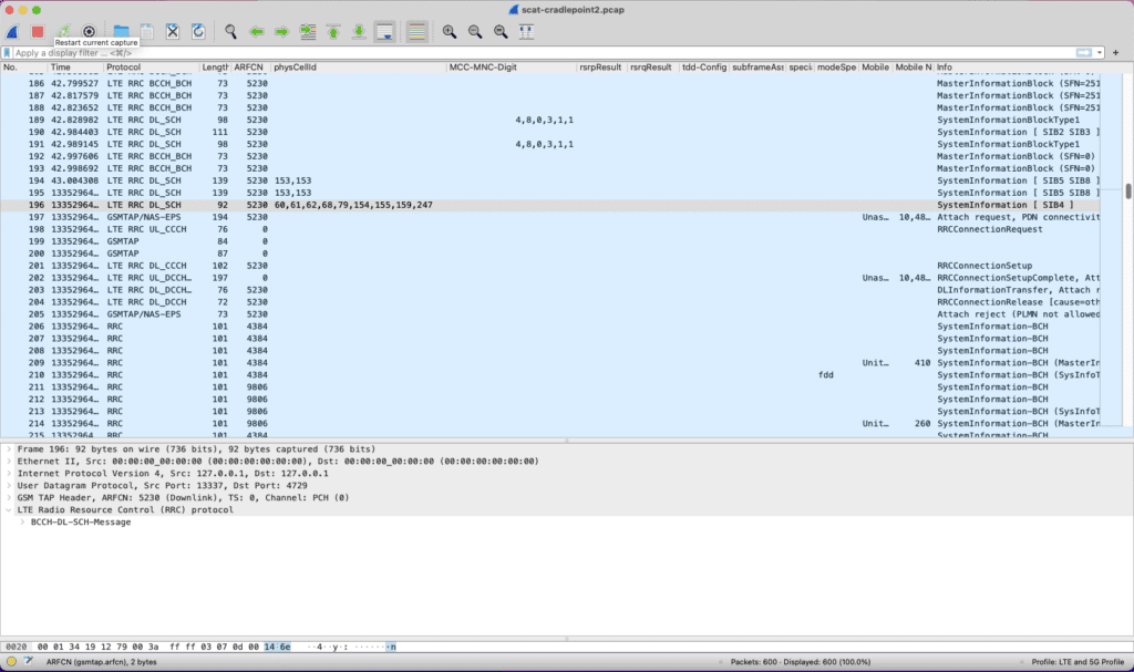
After my previous posts about QCSuper, I have since realized there is a small bug with the GSM Tap Header of a 5G Qualcomm modem. In running QCSuper or SCAT, the packet captures have the ARFCN field set to 0. This limits the capture because what Band the traffic was received on is lost. In reading the issues on SCAT’s Github page, the cause came into focus. My original custom USB Modem is running a Qualcomm X55 Snapdragon 5G modem. Because of some of the changes with 5G, this traffic doesn’t get recorded and passed down to the GSM Tap Header so that information is lost. If you run this tool with a 4G LTE Modem, such as the Cradlepoint MC400-1200M USB that has a Telit LM960A18 PCIE modem as in my above pictures, then it captures that information. Like the screenshot below shows, the ARFCN column field is populated on some frames when using this combination of the tools. 5G captures and PCI Scanning is currently not supported by neither QCSuper nor SCAT.
SCAT as a PCI Scanner
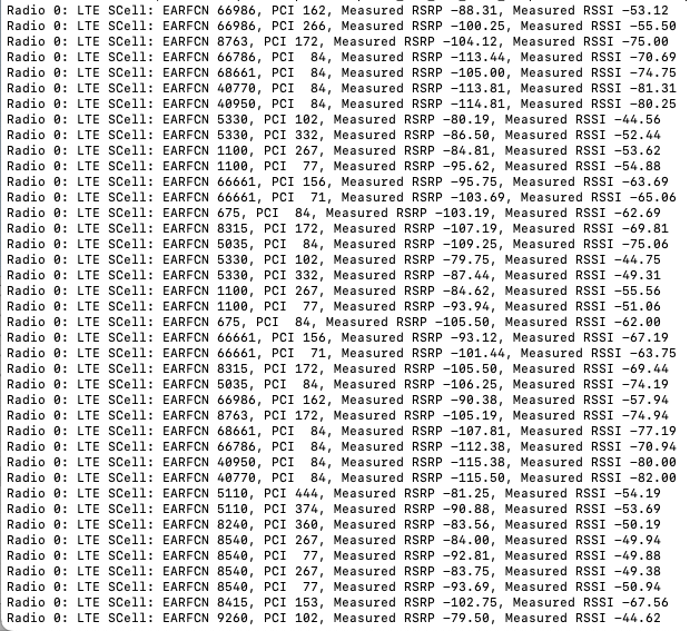
So let’s dig into what SCAT is showing us from the view of a PCI Scanner. The tool output displays 5 columns. The first column tells us what Radio heard the traffic, for me this has always been Radio 0, along with the technology the traffic is using, in this case LTE. If the tool was updated to support 5G, it would show 5G in this column.
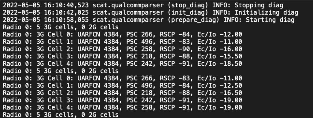
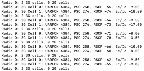
I have received some traffic showing 3G as displayed in the screenshot below. 3G, 4G LTE, and 5G use different readings so the tool shows information according to the technology. For example, 3G uses UARFCN, while 4G LTE uses EARFCN, and 5G uses NEARFCN to represent the spectrum channel.
In the PCI Scanner results, the next column is that SCell EARFCN column. SCell stands for Secondary Cell, which means it is using Carrier Aggregation off the PCell or Primary Cell. SCAT uses the secondary cell to run the scan. If you take the EARFCN number and plug it into a ARFCN calculator such as the one at https://www.cellmapper.net/arfcn, it will tell you the matching frequency channel number. For example the first row below shows EARFCN 5230. Punching that number into CellMapper’s calculator, it tells us that EARFCN 5230 translates to Uplink Channel 782 MHz and Downlink Channel 751 MHz.
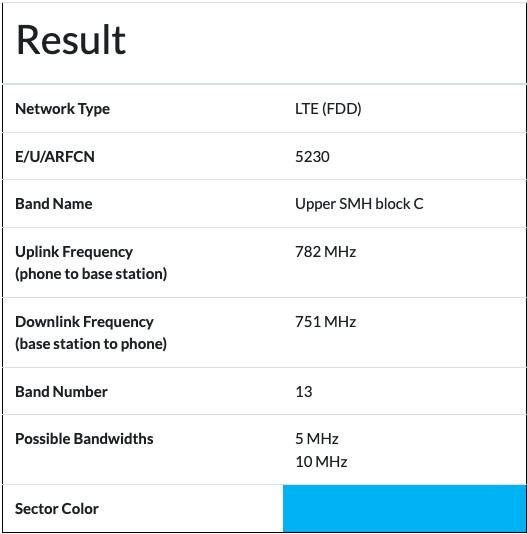
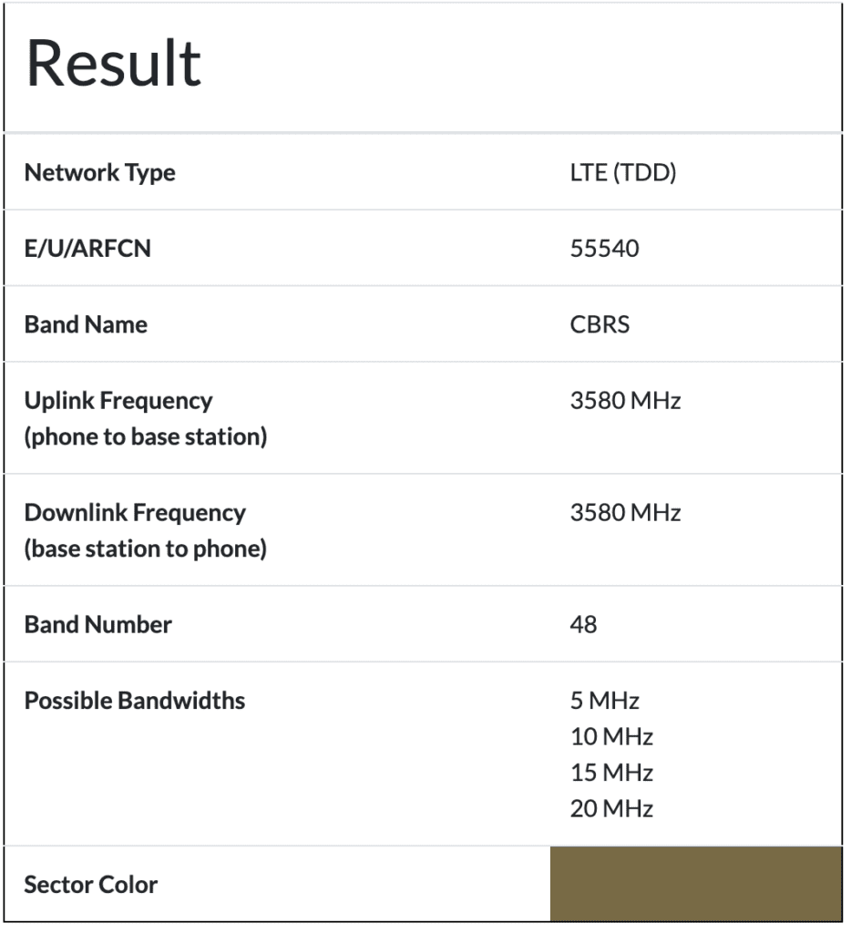
In a lot of the cellular bands FDD is used, while the CBRS Band uses TDD. This example captured frame is from a carrier using FDD, where the uplink and downlink channels are using different dedicated sections of the spectrum. The CBRS band uses TDD which separates uplink and downlink traffic based upon a timed scheduled pattern of uplink and downlink slots as I explained in my previous post. The screenshot above shows FDD and the screenshot below shows TDD from that CellMapper calculator for two different EARFCNs.
The third column of the PCI Scanner results is some of the most important information gathered from a PCI Scanner. PCI stands for Physical Cell Identifier. The PCI field helps the UE with Downlink Synchronization.
In regard to gleaming information from the PCI, the PCI field helps you narrow down which physical radio on a tower that is broadcasting the traffic. If we use the Cellmapper.net map, we can start to find the PCI value of different towers and find which tower sent that specific frame.
The last two columns tell us important information about the measured RSRP or received power and the measured RSSI or received signal strength. This information is useful to measure how well a signal is received in a location to determine dead spots or to start building coverage maps.
Finally, after putting all that information from the PCI scanner together, using Cellmapper.net, I’m able to narrow down what carrier sent that FDD frame, what channels were used, and even the specific tower.
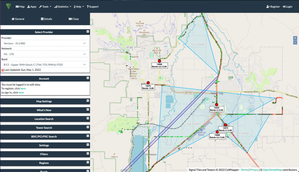
When I go to cellmapper.net/map and zoom into the map of my area. I can find that Band 13 (B13), pulled from the EARFCN calculator, is used by Verizon. There are several towers surrounding my area so I’m not sure which tower broadcast that specific frame.
Next, I can start digging into the individual towers to look for PCI 153. By selecting the tower at the center of town, we find PCI 153 under Cell 1 of the details tab. If you look at the Uplink Channel 782 MHz and Downlink Channel 751 MHz, they match perfectly with the information pulled from the received frame.
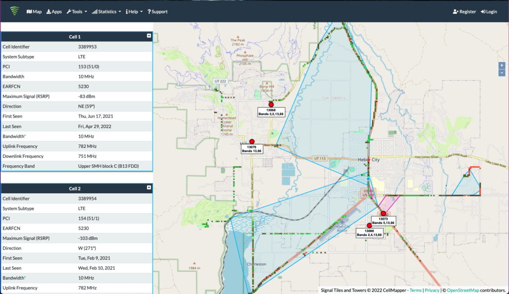
The example frame captured in the screenshot below, is a Verizon Band 13 MIB with EARFCN 5230, Uplink Channel 782 MHz and Downlink Channel 751 MHz, PCI 153, RSRP of -91.19dBm and RSSI of -57.19dBm. The Cell Identifier is 3389953 for that specific radio on that specific tower in the center of town.
All of that information can be gleaned using SCAT as a PCI Scanner. Obviously, this relies on crowd sourced information from CellMapper’s app. Most CBRS networks are not registered carriers with their own PLMN codes so tracking them down to a specific tower is not that easy. That is going to require additional access to controllers or a Spectrum Analyzer which my 5G/LTE Modem cannot provide. But this gives better information and insights than I had before.
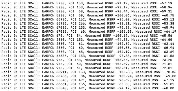
The CBRS Networks are captured by the PCI Scanner as show below. Sometimes, it will lock onto a network and only show information for that network for a while. Eventually it does show additional networks. This can be useful in measuring the signal of a specific network and for finding dead spots while walking around with the PCI Scanner.
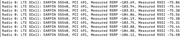
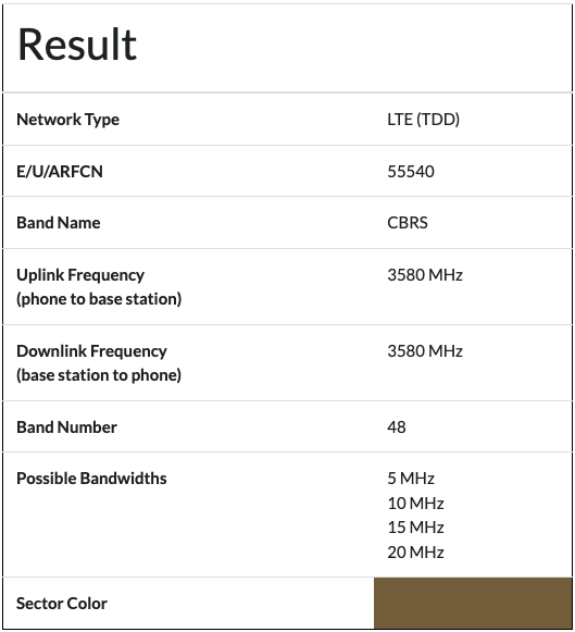
The PCI Scan results of the network above is EARFCN 55540 which translates to the CBRS Band 48 (B48). Since CBRS is TDD, the Uplink and Downlink channels are the same, 3580MHz. PCI 491 is a number given to my radio so unlike the carrier radios, you can’t rely on a public database to identify it. You would have to look in your own controllers and systems to ascertain that information. The RSRP fluctuates between -103.69dBm and -106.12dBm. The RSSI fluctuates between -75.06 and -76.50.
In building CBRS networks, it is recommended to plan the assignment of PCI codes very carefully to avoid overlap. Without a proper PCI Plan, there may be PCI collisions and conflicts that can cause network performance issues. A proper PCI Plan can improve the network operations. The range of codes for LTE PCI is 0-503, so there are only 504 values available, so planning a Small Cell network such as CBRS becomes important. If you run into an issue and need to determine which radio is broadcasting, having unique PCI codes may also help alleviate some unneeded headaches.
SCAT: LTE Packet Capture
The other piece of the SCAT Tool is the logging to PCAP files. As I mentioned at the beginning, adding the -F /path/to/file.pcap flag to the scat command causes the tool to capture the Layer 3 Frames to a file. This tool operates almost exactly like QCSuper. The files captured may include a little different information sometimes. Sadly, you can’t run both, QCSuper and SCAT, at the same time without two different modems. But SCAT does the packet captures with the additional PCI Scanning, so it’s becoming my go to tool.
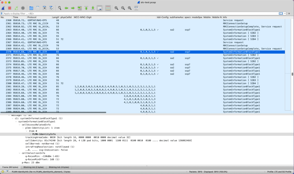
Since my previous blog about QCSuper, I’ve added some additional columns to my Wireshark profile. As I mentioned before, the ARFCN and PhysCellId (PCI) were not being passed to the GSM Tap Header or being captured because of an issue with a 5G modem. This is solved by using a LTE modem, instead of a 5G modem, as you can see in the screenshot below. The Physical Cell Id column can include multiple PCIs or a single PCI based on the received frame and tower broadcasting.
In the screenshot above, Frame Numbers 194 and 195 have PCI 153 and ARFCN 5230. In continuing with the above example of the PCI Scanner, those frames with the PCI of 153 are from Verizon. Those frame captures results correlate directly with the traffic in the PCI Scanner app.
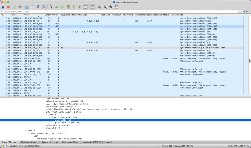
When it comes to CBRS networks, the PhyCellId and ARFCN hasn’t be captured in the PCAP files using SCAT in my testing. So you have to rely on the PCI Scanner to ascertain the networks that are being broadcast. The grey highlighted Frame Number 343 below, shows ARFCN of 0, but it did include the PhyCellId of 50 under SIB5. Digging into what is relayed in SIB5, this is the PCI of a neighboring network, not the broadcast network of the radio we are looking for. This is to aid a device in roaming between radios. Since the column is named the same, it showed up on this individual frame.
Wireshark still doesn’t have full support for LTE/5G traffic, and as we see with the 5G radios this isn’t foolproof. That said, it is capturing important information that is useful when troubleshooting a LTE network. I’m attempting to build a Wireshark Profile with color rules, like the Metageek Eye PA rules for Wifi. Since these are IP traffic Packets, it’s marking all the traffic the same color. So we’ll see if I can build a color rules profile.
War Driving Through Salt Lake City
Once I had SCAT installed, I decided it was time to really test my WLAN Pi Pro. It was time to go on a War Driving excursion through the Salt Lake Valley to see what I could capture. I connected my phone to my WLAN Pi Pro and started SCAT running both the PCI Scanner and Packet Captures. These are some of the results:
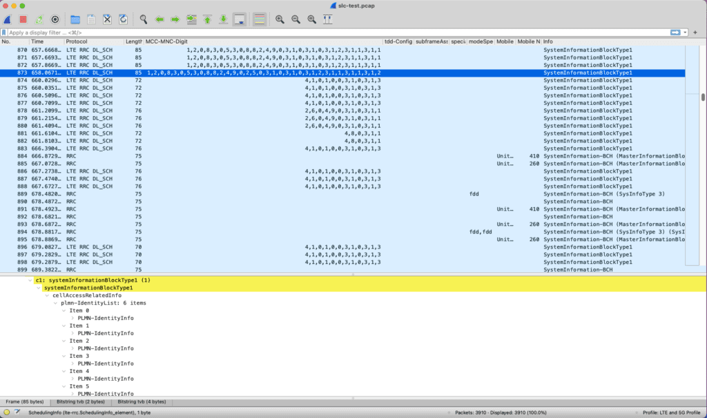
During the War Drive, I captured MIBs from all the major cellular carriers, including a SIB frame from T-Mobile/Sprint that is using all 6 PLMN options. I also found a CBRS network that my device was rejected from joining. I’m not sure if this was one of the schools within my network or someone else with a CBRS network. My next goal is to do a more extensive War Drive now that I have the EARFCN and PCI solved with a LTE modem instead of my 5G one.
In my next post, I’m going to dig deeper into these packet captures, specifically the MIB, SIBs, and the UE Authentication process.