
Welcome to my new theme on my website. I’ve been redesigning the website for my day job. I decided that I should make my blog work better for finding old content so here it is. My previous theme was just used to get my blog up and running quickly. It’s now time for something new!
In the spirit of new, it’s been a while since I talked about the CBRS Pi. CWNE #500 and Wifi took my attention the last few months. A few nights ago, after a record breaking 900+ feet of snow this past winter, I went for one of my first of the season drives up in the mountains amongst the green aspen and pines. I drove past sites, that last year I was using Starlink with CBRS to do some tests, and it got me thinking.

Interest in understanding Private Cellular Networks (PCN) is increasing. More people want to know how to create these networks and measure them. That is leading me to wonder how to actually use the data captured from the CBRS Pi and consume the data in a more usable fashion. Whether, I am capturing in the mountains or in a school building.
CBRS Pi

As a quick update, the CBRS Pi is my personal project for bringing cellular measurements of Private Cellular Networks (PCNs) to more people. Carrier grade tools such as the PCtel IBFlex or Epiq Prism are out of the range of most without deep pocket books, especially when starting out. More Wifi Engineers are beginning to learn how LTE and 5G work in the CBRS band or the other bands available in other countries. We want to see the technology at work and be able to measure it.
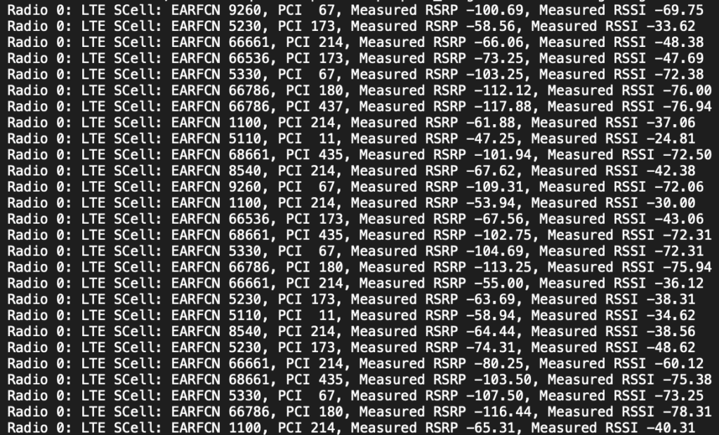
My main way to use the CBRS Pi has been to capture cellular PCAPs using SCAT and QCSuper. Both tools are excellent for that purpose. It doesn’t make accessing the data at the time of capture very easy though. SCAT has a PCI Scanner built in, that displays information it captures in the terminal, that I’ve been able to run on a phone connected to the CBRS Pi. It outputs data like this:
Cellular Bands
When you start SCAT, it uses whatever Bands the modem is capable of and configured to use. As you can see in the screenshot above, the EARFCNs are all over the place as this capture wasn’t limited to a single band. You can use the Frequency Calculator on Cellmapper.net to figure out what spectrum that is being captured. EARFCN in LTE and NARFCN in 5G are a mathematical representation of the Band depending on FDD or TDD.
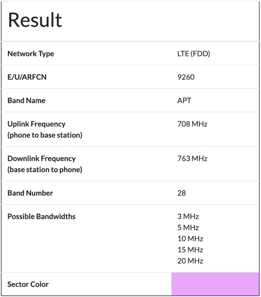
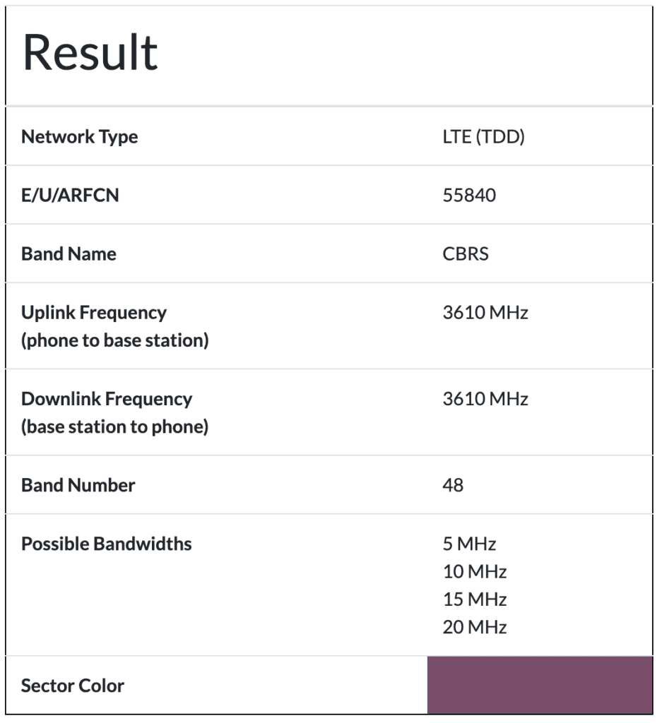
The screenshot below, shows the Uplink and Downlink are on different channels. Because of that difference, we know this capture is using Frequency Division Duplexing (FDD). CBRS uses Time Division Duplexing (TDD), or alters the uplink and downlink based on different timing schedules. TDD networks, like CBRS, uses the same frequencies for both uplink and downlink.
For example, from the PCI Scan above, EARFCN 9260 is 708 MHz Uplink and 763 MHz Downlink. This example is a licensed broadcast of one of the carriers networks.
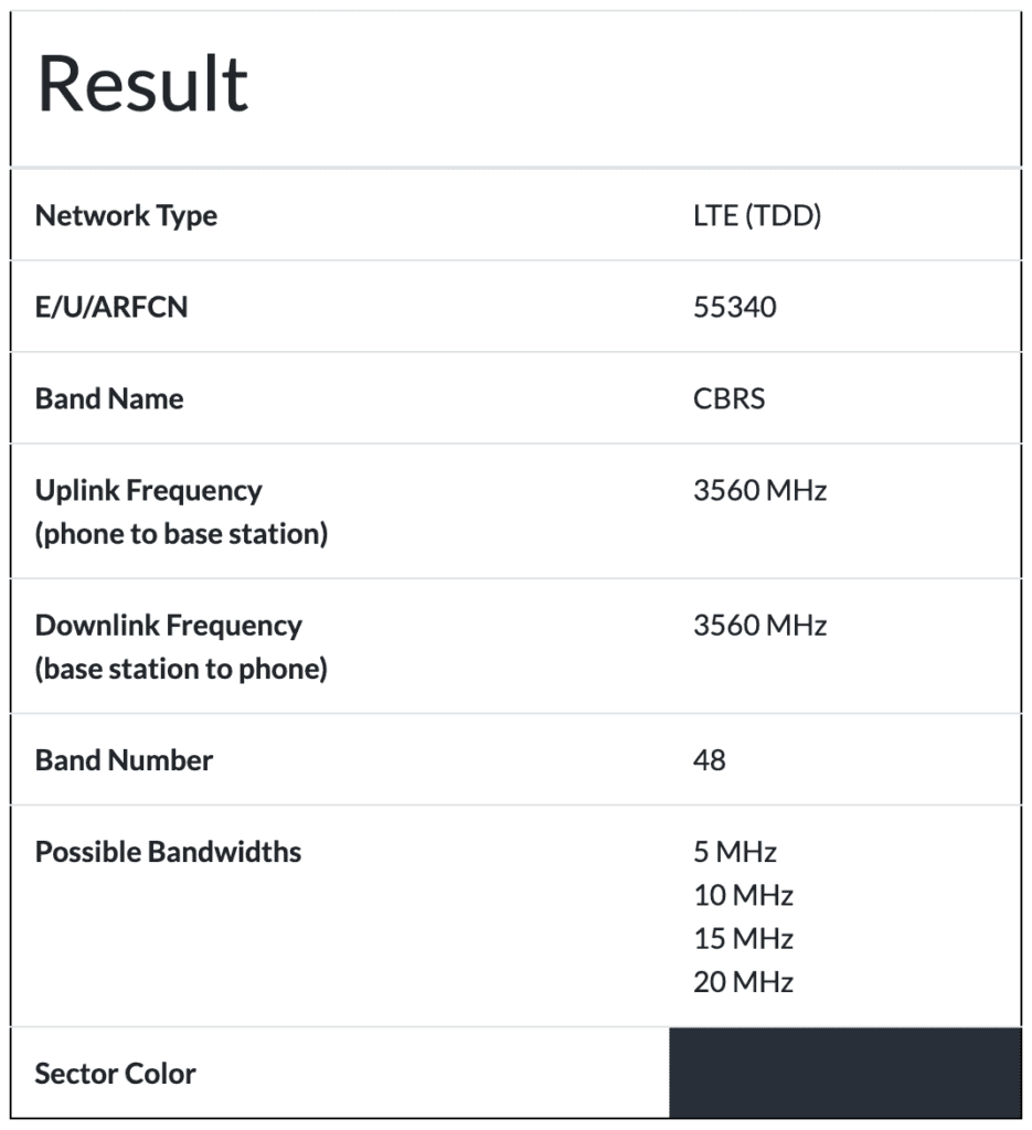
Another example, from another PCI Scan below shows EARCN 55340. This is a scan of a CBRS network.
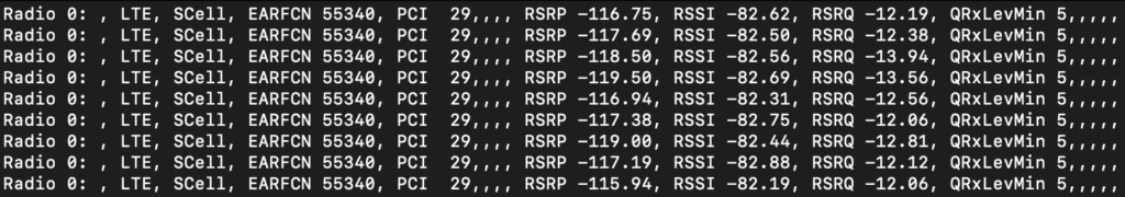
Putting that in the Frequency Calculator, we find it is 3560 MHz on the Uplink and Downlink. This is a TDD network. TDD frequencies range from Bands 33-53, of which the CBRS Band 48 falls within.
You can do that math with any of the EARFCN captured by SCAT. Like last year, while capturing with the CBRS Pi up the canyons where I went this past week, I cared about the bands the carriers were using.
When I am only testing my Private Cellular Networks, I don’t care about the carrier bands. I only care about the CBRS Band 48 or EBS Band 41. Last October, when I was in Prague, I was talking with people at WLPC Prague about this very issue. So, I set out to figure out how to limit these modems to a single band.
Narrowing Down the Bands
That lead me to start looking at the AT Commands of the Cellular Modems that I’ve been using. To send AT Commands to the cellular modem, you need to use a serial port communications program. I personally use Minicom.
To install Minicom, run the following on your Linux or CBRS Pi:
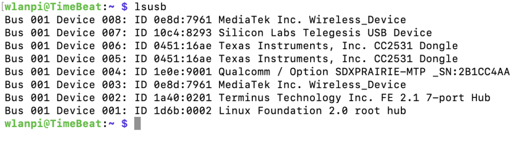
$ sudo apt install minicomYou need to make sure your modem is serial accessible via USB. First let’s look at the results of the command lsusb. That should list the USB devices attached to your CBRS Pi. On my device, the modem is the “Qualcomm / Option SDXRAIRIE-MTP _XS:2B1CC4AA” in the list. I have a couple Comfast CF-951AX and a couple Bluetooth dongles plugged into my device.
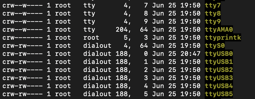
Next lets look in the /dev folder with the cd /dev command and then issue the ls -l command to show the contents of the folder. In that /dev folder there should be some tty devices usually ttyUSB0, ttyUSB1, ttyUSB2, etc. If you see those items listed we should be good to go.
Then to access minicom to enter the AT commands, run the following command:
$ sudo minicom -b 115200 -D /dev/ttyUSB2You’ll want to make sure Echo is enabled so you can see the commands as results as you type them. Type CTRL-A then Z keys. That will bring up the menu below. As you can see to turn on “local Echo on/off..E” press the E key. So, type E. That will take you back to the main minicom screen.
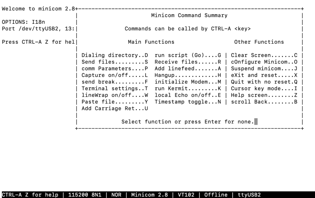
Now when you type into the screen it will display your commands.
This part is where it will be different from Modem to Modem. I have several different types of modems and the following commands are different from vendor to vendor and even modem type to modem type. Depending on the modem, these are often a one time set it commands, until you need to change the band again later.
There are some standardized AT Commands but the majority of the commands we are interested in are specific. The best solution is to search for the AT Command list for your specific modem. I’ll include a few different modems below.
From my testing, I find it better to only set a single band when using the tools I talk about below to ensure you capture the desired data. These modems support so many bands, you might miss data you are looking to capture. Additionally, many view some of these tools as hacking tools, just like many Wi-Fi tools have been branded. Narrowing the modems to only scan a single private Band limits the scope to avoid capturing unneeded data that could lead to legal issues.
On the SIMCOM 5G modem, enter the following command to enable LTE Band 48, CBRS only. The SIM8200EA-M2 modem AT Commands can be found here.
AT+CSYSSEL="lte_band”,48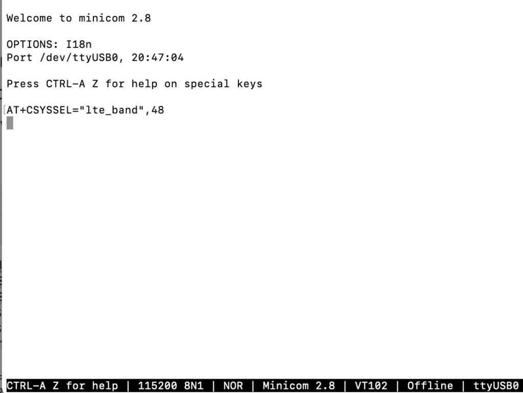
You can also set it to 5G NR with the following command. This sets both 5G Band n41 and n48. If you want to enable other bands enter the number then a colon like ,41:48 instead of comma 48.
AT+CSYSSEL="nr5g_band”,41:48On a Sierra Wireless modem, enter the following command to enable Band 48, CBRS only. To enter different bands together you have to do HEX math and add them together. The specific commands for the Sierra Wireless AirPrime MC7411 are found here.
AT!BAND=09,"Band 48",0,0000800000000000On a Telit modem, enter the following command. The Telit modem AT Commands list can be found here.
AT#BND=0,0,800000000000On a Quectel modem, enter the following commands based on LTE, 5G NSA, or 5G SA. The Quectel RM520N-GL modem AT Commands list can be found here.
AT+QNWPREFCFG=“lte_band”,48
AT+QNWPREFCFG=“nsa_nr5g_band”,48
AT+QNWPREFCFG=“nr5g_band”,48
The Quectel was similar to the SIMCOM modem in that you can separate multiple bands with colons.
AT+QNWPREFCFG=“lte_band”,41:48Once you enter the command specific to your modem. Type Ctrl-A then Z then X to exit out of minicom. With most modems, you will need to restart the device. Type sudo reboot to restart the CBRS Pi. Some modems have AT commands that you can use that will just restart the modem not the whole device. Some modems I’ve had to completely turn off the device and do a hard power off/power on before the AT command would take effect.
Testing the Band Lock
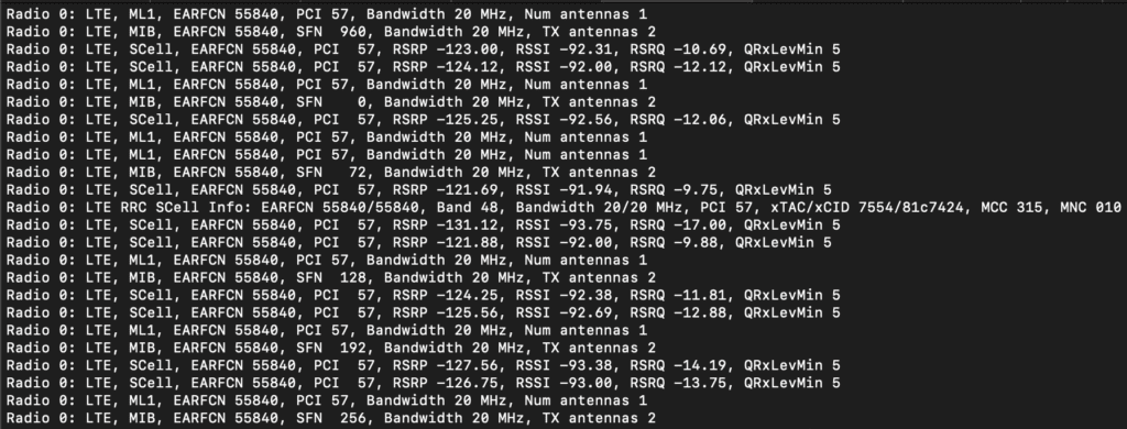
Once the modem or device is restarted, you should be good to go. If you run the scat tool now, it should only capture traffic on the specific band that you just configured. As the screenshot above shows, it is only capturing EARFCN 55840 which is Band 48 as shown from Cellmapper.net.
During this capture, at my house I have two radios from my day job on Band 48 within range. The 55840 radio was stronger than the other one but it would occasionally capture the data from the other radio, with a super low RSRP less than -120dBm. The signal from both are barely enough for clients to connect.
Also be sure to remove any SIM cards from the device. If a SIM card is installed, the modem will attach to the first radio it is authorized to join. It will not show any additional networks unless you are moving around and it selects a new cell. Without a SIM card, the modem doesn’t know where to attach. So, it just scans for available networks. This is why we need to limit the device a single band. Otherwise, there are so many bands that you start missing data. If you want to scan multiple bands, I recommend you use multiple modems, each configured for the specific band. The CBRS band has only fifteen 10MHz channels, but devices do not jump between bands very easily.
LTE_Search
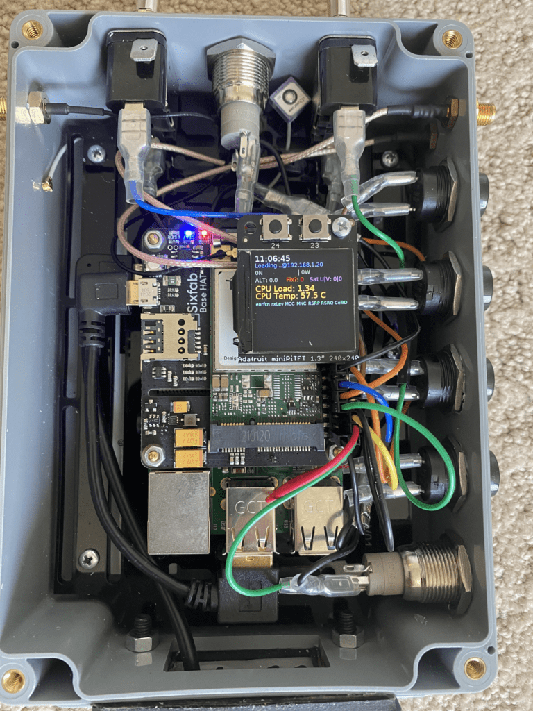
In addition to the SCAT tool, I found an application called LTE_Search that is useful for writing and reading AT commands via Python code. The purpose of the code is to be a PCI Scanner and attaches GPS coordinates to the results. It shows the data in a csv format that can be used in lots of ways. This code displays the data to an Adafruit miniTFT 1.3″ screen. The picture below is from the project’s Github.
The installation instructions on Github are missing required dependencies. The instructions to install the missing dependencies, I posted under the open issue on the Github. I should probably help merge those into the main documentation at some point.
The bigger issue with this code is that LTE_Search uses a group of very specific AT commands that only works on certain Telit modems. The AT command will output a comma separated string that the program uses to output the data. I have a couple different Telit modems and they support some of the used AT commands while not supporting others. Modifying it slightly I was able to get some usable data. It’s not working as fully as expected because of those commands from the code do not work when I test them in minicom on my Telit modems.
I attempted to purchase the mentioned Telit modem that accompany the SixFab Pi Hat as he talked about his in blog posts. I was hoping to reproduce this application. The mentioned Telit LE910C4-NF doesn’t support Band 48, but that was less important to me for this exercise. When the SixFab Hat and modem arrived, I received a Quectel modem instead, that also doesn’t support Band 48. The purchase wasn’t all bad. I got another SixFab Pi Hat out of it though and a modem I can use to test carrier bands with SCAT or another project that I’m working on.
I recently purchased a new modem from Quectel. In researching the AT commands to lock it to Band 48, I found some additional AT commands that might be useful for this tool.
AT+QENG=“servingcell”
AT+QENG=“neighbourcell”
While I can’t reproduce the results of this program exactly because of a different modem, theres some pieces to this application that are going to be helpful. This is definitely going to be useful for the future of this project. I’ll dig into this tool deeper in a future blog post.
Modifying SCAT
SCAT solves the big issue of using AT commands that aren’t available from modem to modem. It doesn’t use AT commands. It talks to the modems with other methods to retrieve data. While this isn’t useful to set the Band; it works great for reading diagnostics data from the modem. Using both tools will be helpful in the future.
The team that is creating the SCAT tool have been actively updating the tool. When you run the SCAT tool it provides some additional information now. The default variables the SCAT tool displays are which Radio data is captured on (usually Radio 0); the technology (either 3G or LTE); the Cell (either PCell for Primary or SCell Secondary); the EARFCN for LTE, the PCI or Physical Cell ID of the broadcasting radio; and the Measured RSRP and Measured RSSI. Depending on additional frames that are captured, it shows additional data such as the MCC/MNC, TAC in HEX, Cell ID (CID) in HEX, Bandwidth, amongst others.
It currently doesn’t capture 5G traffic, even if the radio used supports 5G. I’ll get into more on that in my next post. This is a time and coding issue more than a technical issue that largely is a Wireshark issue. I’ve been trying to figure out how to get the diagnrlogparser.py to output data to the terminal like the other parsers do with LTE traffic. Others have caught onto this idea so hopefully we at least get this data soon enough.
Next, I started to dig into the application code. I soon realized the SCAT tool was capturing but not displaying more variables that are useful information to display to the screen with the default variables. At that point it was a simple Python coding exercise to manipulate and output that additional data.
I’ll dig into those details on my next post. I also will talk about how I’m starting to use this data in meaningful ways.